Home / Liquid Cooling Manifolds

Liquid Cooling Manifolds

Liquid Cooling Manifolds

Custom stainless manifolds for rack, row, CDU, and facility-side distribution.

Drawing-based build
Protected delivery

Where it fits

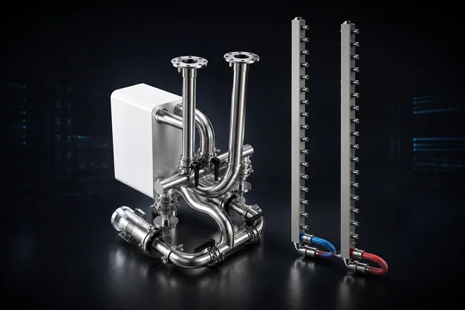
Drawing-built manifold hardware for customer-defined liquid cooling loops.

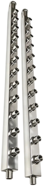
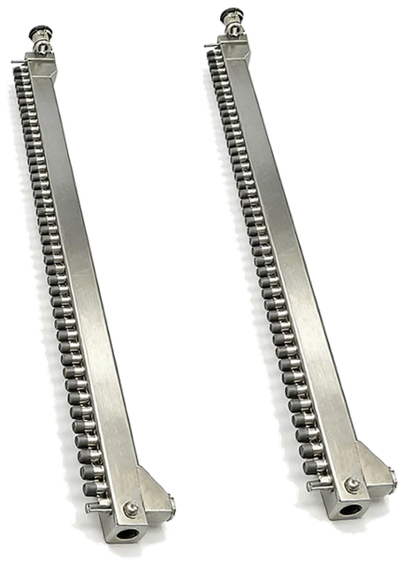
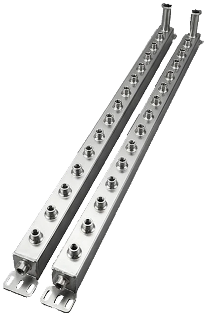
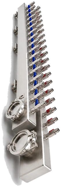
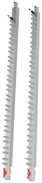
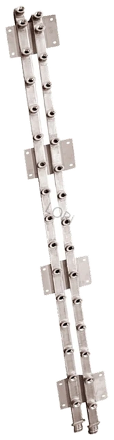
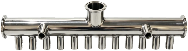
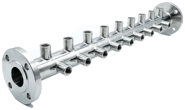
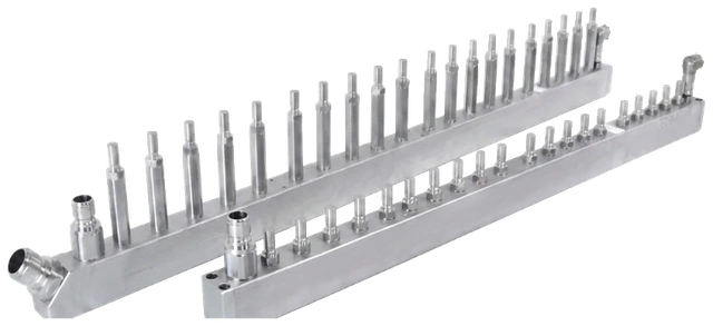
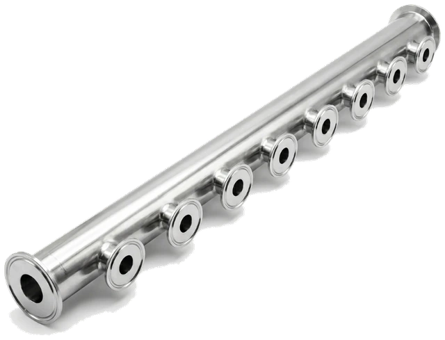
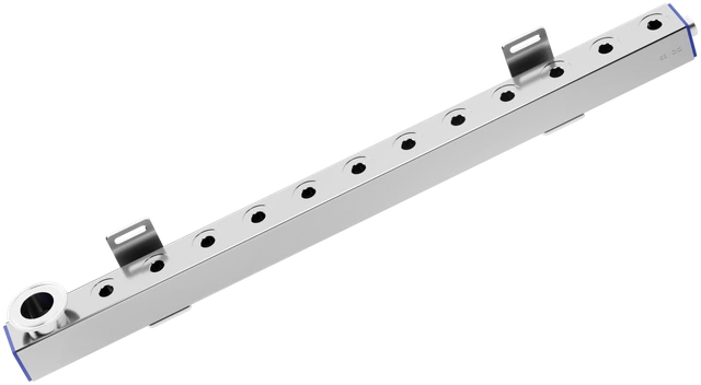
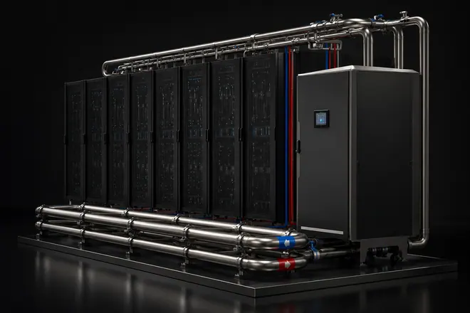
A manifold turns customer-defined supply and return paths into a physical interface for rack, row, CDU-side, and branch connections.

[01]

Rack-side interface

  • Branch connections to rack or server-side cooling loops
  • Port pitch, hose direction, and service access matter
  • Supply / return orientation should be explicit

[02]

Loop-side connection

  • Links to CDU-side piping or prefabricated pipe modules
  • Clamp, flange, hose, QD, or threaded interfaces can be used
  • Connection standard should be confirmed early
[03]

Buildable hardware path

  • Valve, vent, drain, bracket, and test boundaries stay visible
  • Cleanliness, test support, labels, and protected delivery are part of the package
  • Suitable for RFQ and detail-page review

Product family overview

Liquid cooling manifold packages built from customer drawings.

01 / Per drawing

Body format

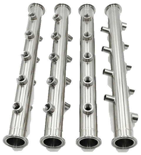
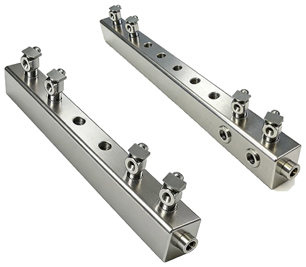
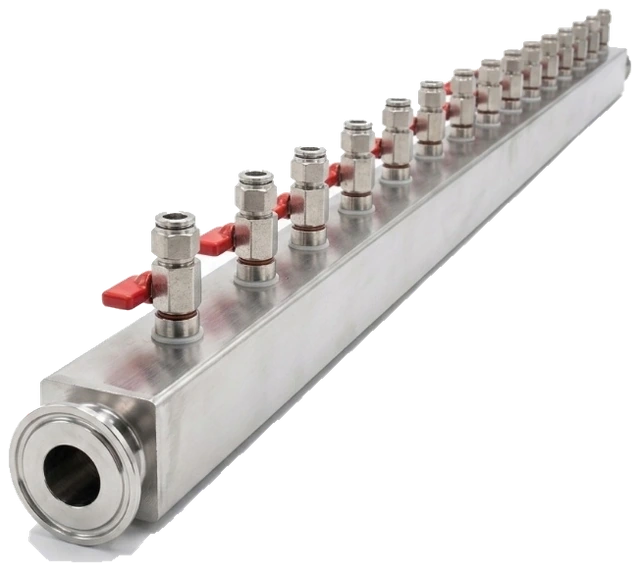
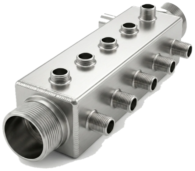
Square-tube, round-tube, machined, or welded manifold body follows the released drawing.

02 / Project-defined

Material basis

Austenitic stainless grade follows the drawing or BOM; certificates and spot checks can be aligned.

03 / Interface package

Interface definition

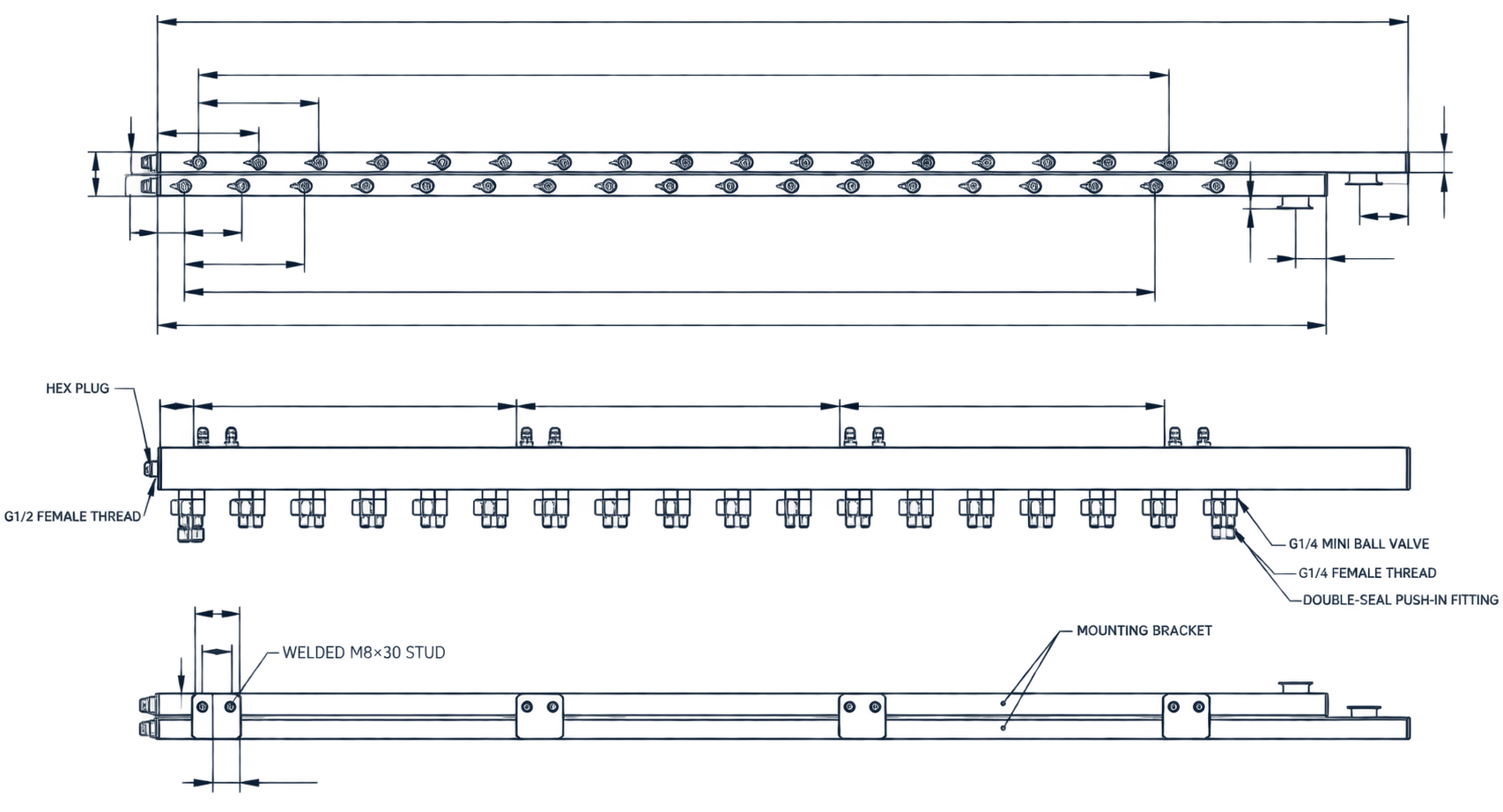
Branch count, orientation, spacing, port standard, service clearance, drain, and vent locations are customer-defined inputs.

04 / When specified

Welding & finish

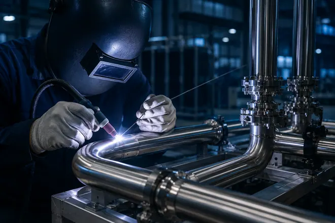
Controlled welding, seal-surface finishing, deburring, and interface protection follow the approved package.

05 / Clean delivery

Cleaning & passivation

Post-weld cleaning, pickling / passivation, DI-water rinse, drying, and capped ports can be included.

06 / Customer protocol

Test & handoff

Pressure / leak test support, labels, packing groups, and export-ready protection follow the customer protocol.

Scope boundary

Customer defines the system. Chelsey fabricates the hardware.

This section keeps the manufacturing scope, interface inputs, and handoff boundary visible without turning the family page into a system-design page.

01

Drawing package

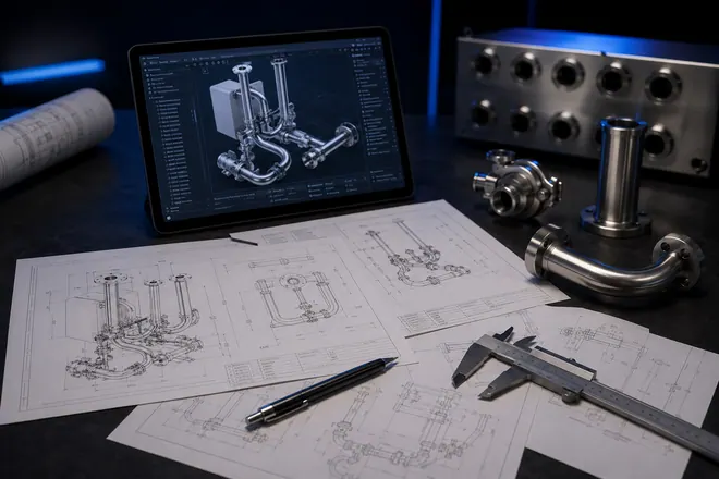
Starts from customer drawings, BOMs, samples, or interface requirements.

02

Interface discipline

Connection standard, material, seals, and component preferences should be confirmed before fabrication.

03

Fabrication support

Stainless fabrication, component integration, cleaning, capping, and labeling stay inside the approved scope.

04

Quality boundary

Test support per customer protocol, packing, and export-ready delivery can be aligned.

Buyer handoff FAQ

Frequently asked questions

01What should be prepared before a product-family review?

Send drawings, BOMs, samples, interface requirements, pressure requirements, component preferences, quantity, and packing destination.

02Does Chelsey define the full cooling system?

No. Chelsey fabricates and integrates hardware within the customer or integrator design package.

03Can customer-specified components be used?

Yes, when the selected valves, quick disconnects, hoses, fittings, or sensors are available and compatible with the approved scope.

04Can testing be included?

Test support per customer protocol, leak review, cleaning, visual inspection, and packing checks can be aligned before delivery.

Send the drawings.We review the build.

Share pipe size, material, pressure, interface type, quantity, fluid medium, customer test protocol, and packing destination for a focused fabrication review.
Drawing / layoutPipe sizeMaterial gradeDesign pressureInterface typeValve requirementTest pressureQuantity
sales@chelseytr.com
+86 180-7217-9517