
Product overview
Liquid Cooling Manifold product details
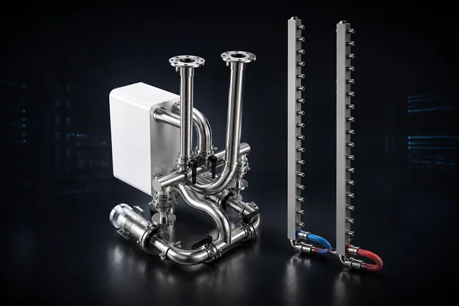
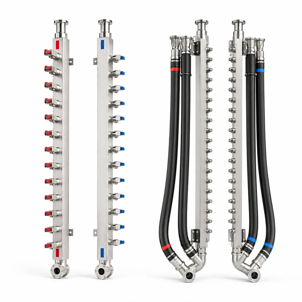
A liquid cooling manifold distributes coolant between the main loop and branch interfaces. Branch count, pitch, port direction, service points, and test requirements follow the released drawing.
Product features
- Branch layout can be built for rack, row, CDU-side, or facility-side distribution.
- Supply / return direction, drain ports, vent ports, and service interfaces follow the project layout.
- Thread, QD, valve, adapter, or hose interfaces can be matched to the approved connection standard.
- Flow consistency, air-tightness, or pressure testing is confirmed by customer protocol.
Specifications
- Branch nodes
- 21 / 24 / 28, or per drawing
- Material
- SUS304 / SUS316, or project-specified stainless steel
- Main loop flow
- 27 LPM - 32.4 LPM, example range confirmed by test requirement
- Branch flow
- 1.0 LPM - 1.2 LPM, example range confirmed by test requirement
- Body size
- 30 x 30 / 40 x 40 / 50 x 50 mm, or custom body per drawing
- Wall thickness
- 2-4 mm, or per drawing
- Connection
- thread, QD, valve, adapter, hose, or project-specific interface
- Service options
- vent valve, mini ball valve, check valve, drain, sensor port
Application
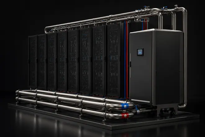
Used in data-center liquid cooling distribution at rack, row, CDU-side, or facility-side pipework. The manifold connects the main pipework with branch interfaces and reserves positions for drain, vent, service, and test access.
Standard functions
- Supply and return distribution.
- Branch outlet alignment.
- Drain, vent, and service port reservation.
- Interface labeling and capped delivery.
Optional functions
Typical applications
Liquid-cooled racks, row-level distribution, CDU-side piping, and facility-side secondary pipework. Final configuration follows the customer system design and site interface package.
Send the drawings.We review the build.
Share pipe size, material, pressure, interface type, quantity, fluid medium, customer test protocol, and packing destination for a focused fabrication review.
