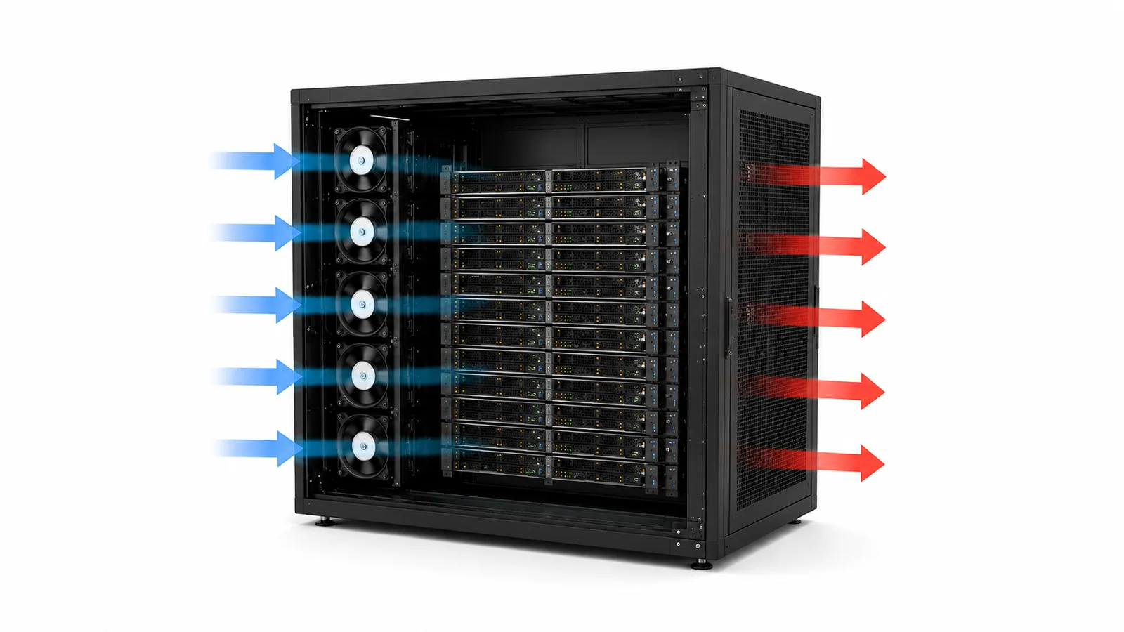
Conventional air path
Heat moves from chips to heatsinks, then into room air. The room cooling system removes that heat from the data hall.
- Airflow and aisle discipline matter most.
- Liquid interfaces are not part of the rack hardware.


Cold-Plate Liquid Cooling
How Direct-to-Chip Cooling Works
Cold plates move chip heat into the technology cooling loop. The CDU keeps that loop separated from the facility water side while transferring heat through its exchanger.
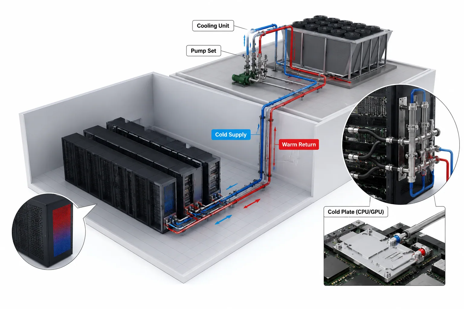
What Changes in the Rack
Air cooling moves heated room air. Cold-plate liquid cooling moves heat through coolant, fittings, hoses, and manifolds. Clear interface data makes the hardware easier to build and test.
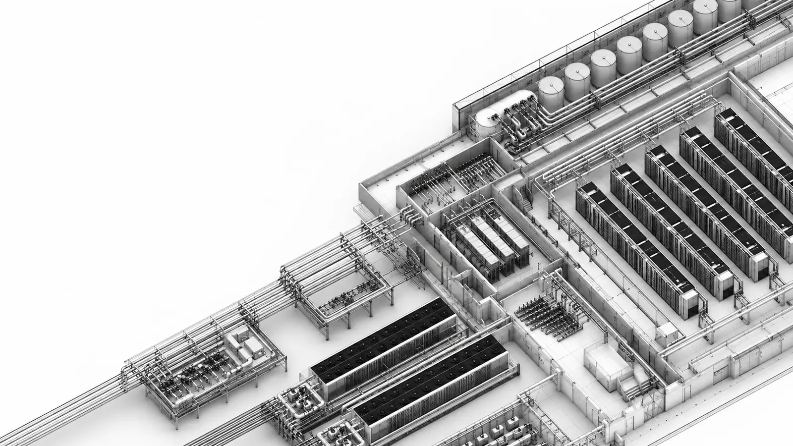
Conventional air path
Heat moves from chips to heatsinks, then into room air. The room cooling system removes that heat from the data hall.
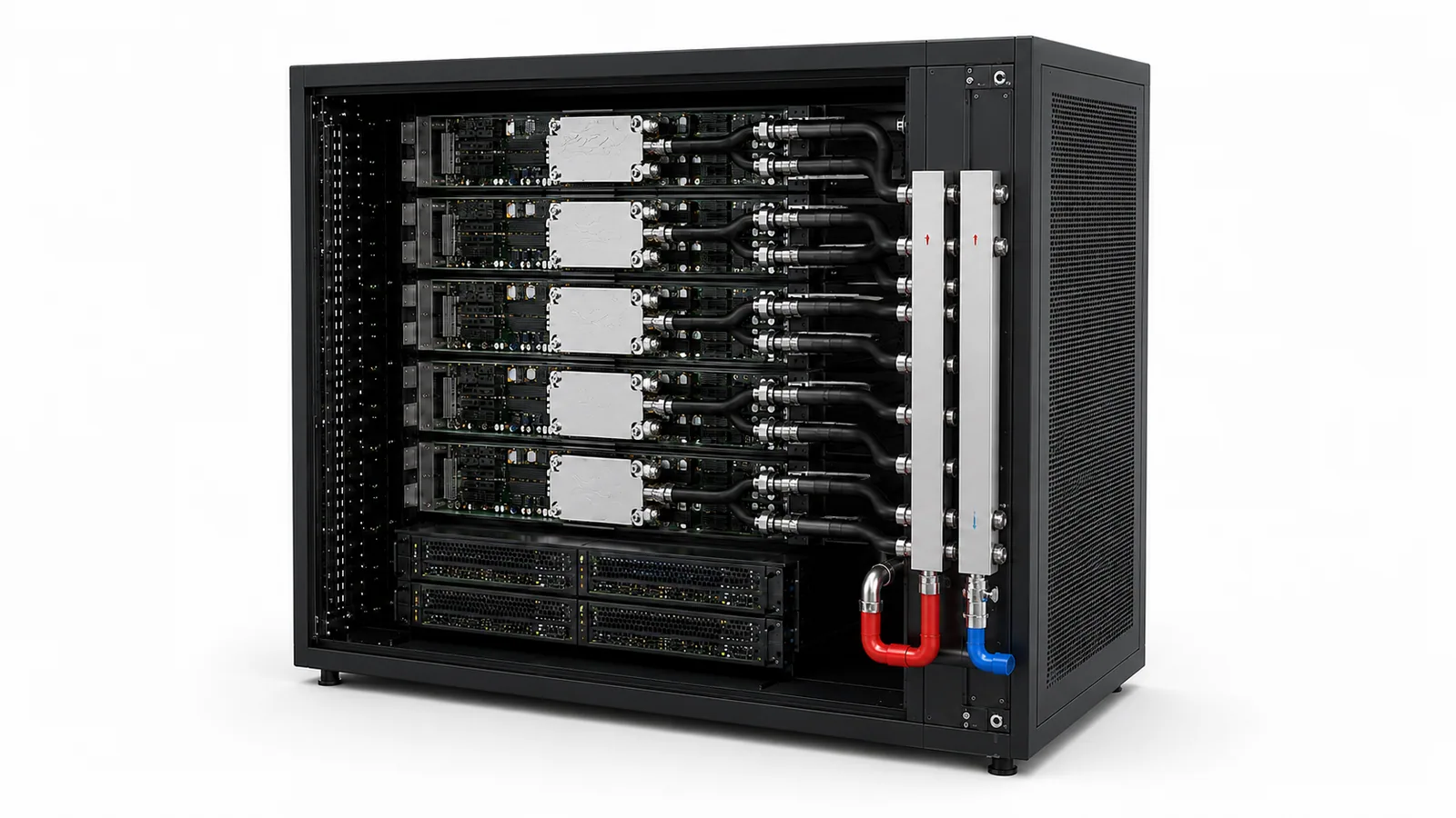
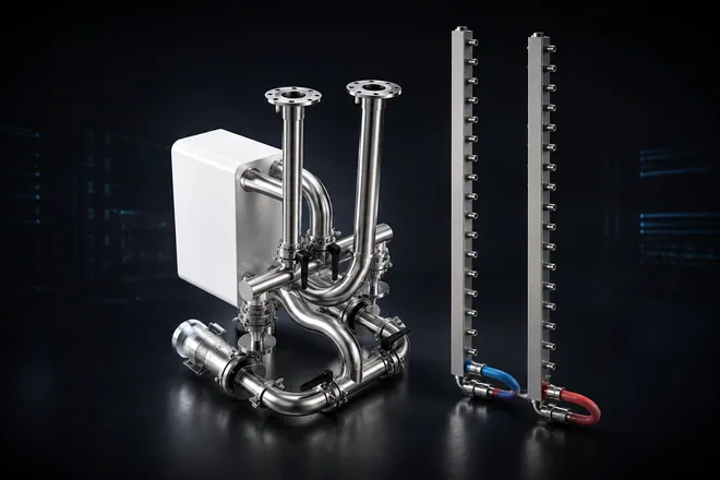
Cold-plate liquid path
Cold plates capture processor heat and transfer it into coolant. Manifolds, hoses, and QDs bring that flow path to a serviceable rack interface.
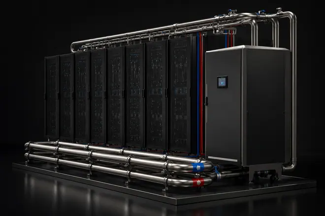
Rack Manifold Environment
A rack interface is not only a manifold. Port order, hose bend radius, QD access, supply/return marking, and bracket positions all affect service work after installation.

After the CDU and cold plates are selected, the rack manifold package still needs practical routing, protected connections, clear labels, and enough room for technicians to work.
CDU-Side Interface
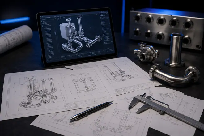
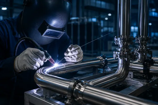
The CDU is normally selected by the customer or system integrator; Chelsey does not claim CDU manufacturing here. Chelsey fabricates the stainless piping, valves, and connection modules between CDU outlets and the row or rack manifold interface.
Project requirements may include general tolerances, geometric tolerances, weld appearance, 1.6 MPa pressure hold, internal cleanliness, and dry delivery. Final acceptance follows the drawings, BOM, and test protocol supplied by the customer.
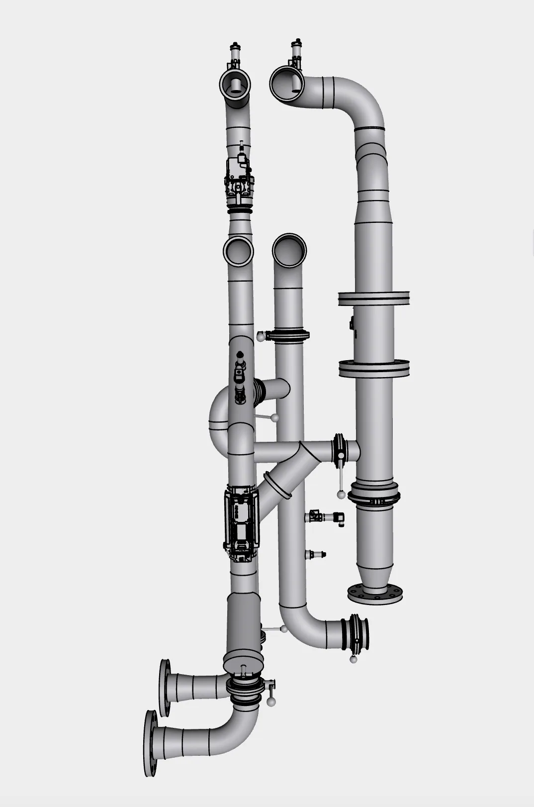
Buildability Details
Liquid cooling problems often start in details: seal type, weld access, cleanliness level, test-port position, and packing protection. Confirming them early makes fabrication and delivery more predictable.
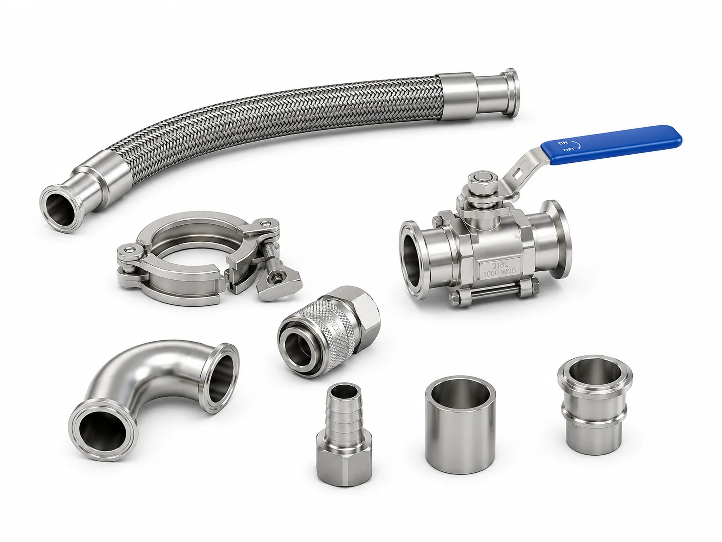
Chelsey Fabrication Role
The customer defines the cooling system. Chelsey turns confirmed interfaces into manufacturable stainless flow-path hardware.
Chelsey does not define the full liquid cooling system, CDU, cold plates, controls, commissioning, or final system acceptance. Chelsey fabricates the confirmed flow-path hardware from customer drawings, BOMs, samples, or interface notes.
FAQ
Yes. Here, direct-to-chip liquid cooling means cold plates transfer processor and accelerator heat into the TCS loop. It is commonly grouped under Direct Liquid Cooling (DLC).
Send drawings or layouts, BOM, interface dimensions, material and connection standards, coolant medium, pressure and temperature requirements, quantity, customer test protocol, labeling rules, packing method, and destination.
No. Customers or system integrators define the architecture, CDU, cold plates, controls, flow and pressure targets, coolant requirements, and acceptance criteria. Chelsey fabricates the confirmed piping, manifolds, and connection hardware.
Share pipe size, material, pressure, interface type, quantity, fluid medium, customer test protocol, and packing destination for a focused fabrication review.