Liquid Cooling Manifold Layout in Direct-to-Chip Systems
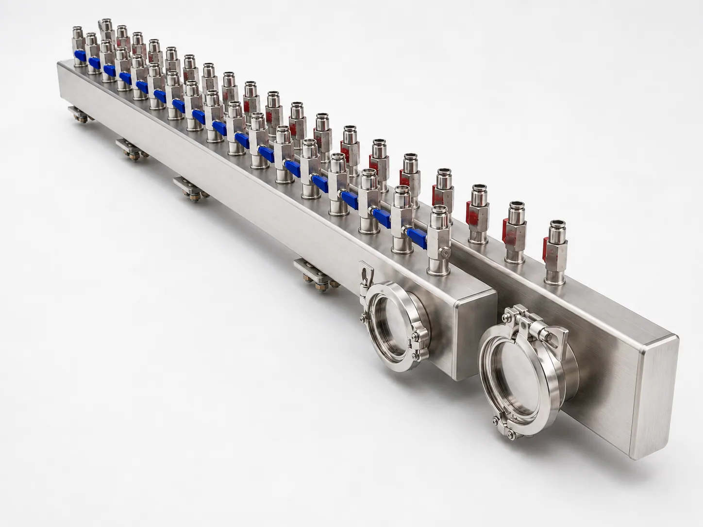
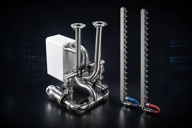
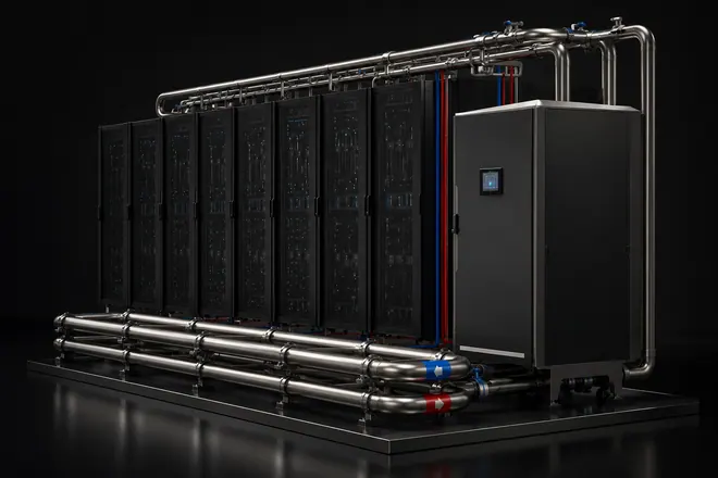
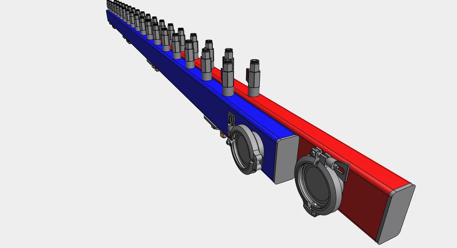
Illustrative in-rack manifold layout showing paired headers, branch valves, and customer-defined end interfaces.
A practical guide to paired supply and return headers, branch layout, service interfaces, mounting points, and drawing-based manifold fabrication.
Explore in-rack liquid cooling manifold fabrication
Short answer
A liquid cooling manifold is a fabricated distribution assembly that organizes coolant supply and return paths between larger cooling loops and repeated branch connections. In direct-to-chip systems, the manifold layout turns a cooling concept into buildable hardware: branch pitch, valve orientation, connector choice, end-port access, mounting, cleaning, labeling, and Test support per customer protocol all need to be visible before fabrication starts.
The manifold is not the full cooling system. Customers or system integrators define the cooling architecture, cold plates, CDU selection, pressure requirements, coolant conditions, controls, installation envelope, and acceptance protocol. Chelsey fabricates the physical stainless hardware from released drawings, BOMs, samples, or interface requirements.
Where the manifold sits in a direct-to-chip loop
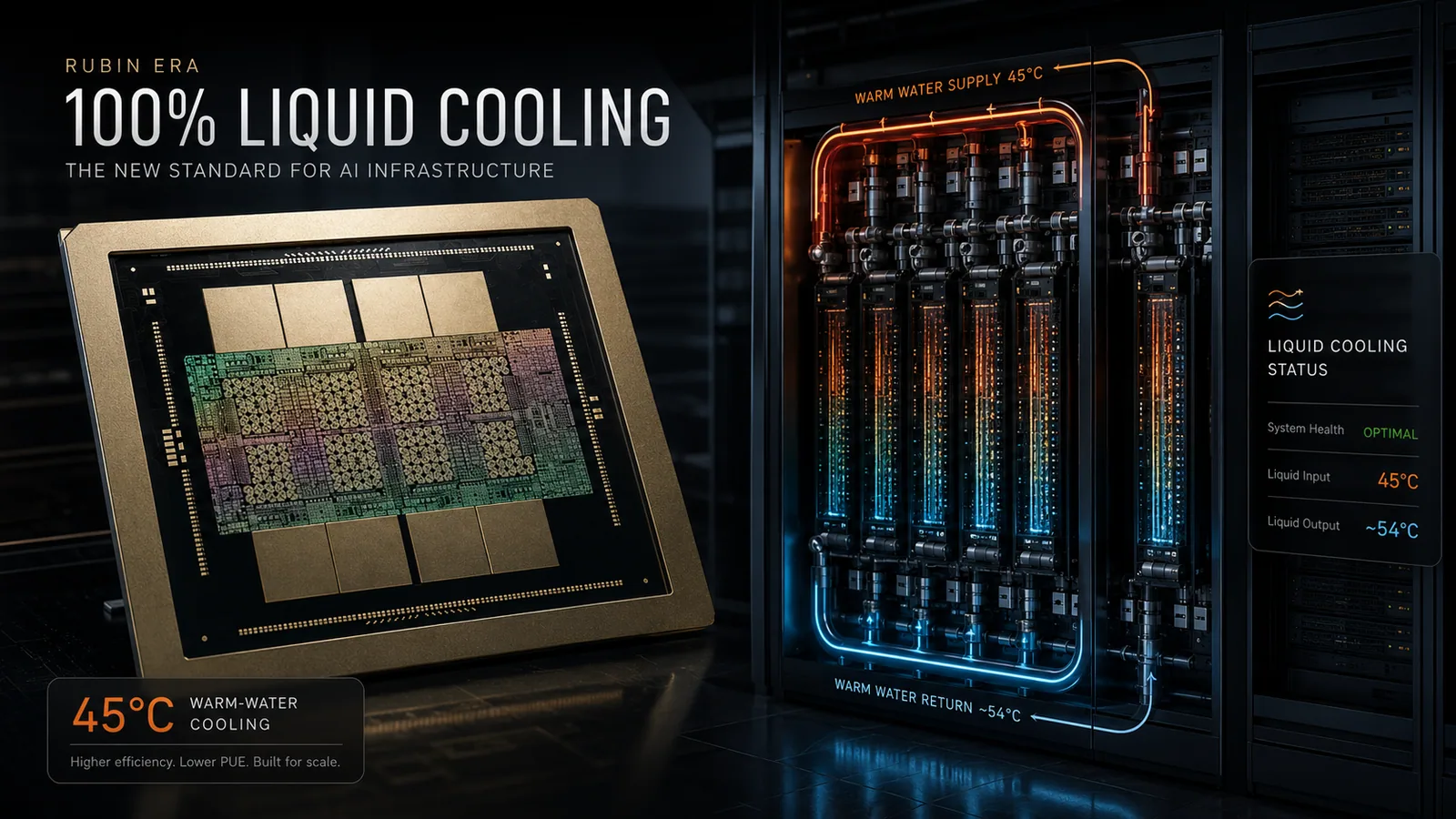
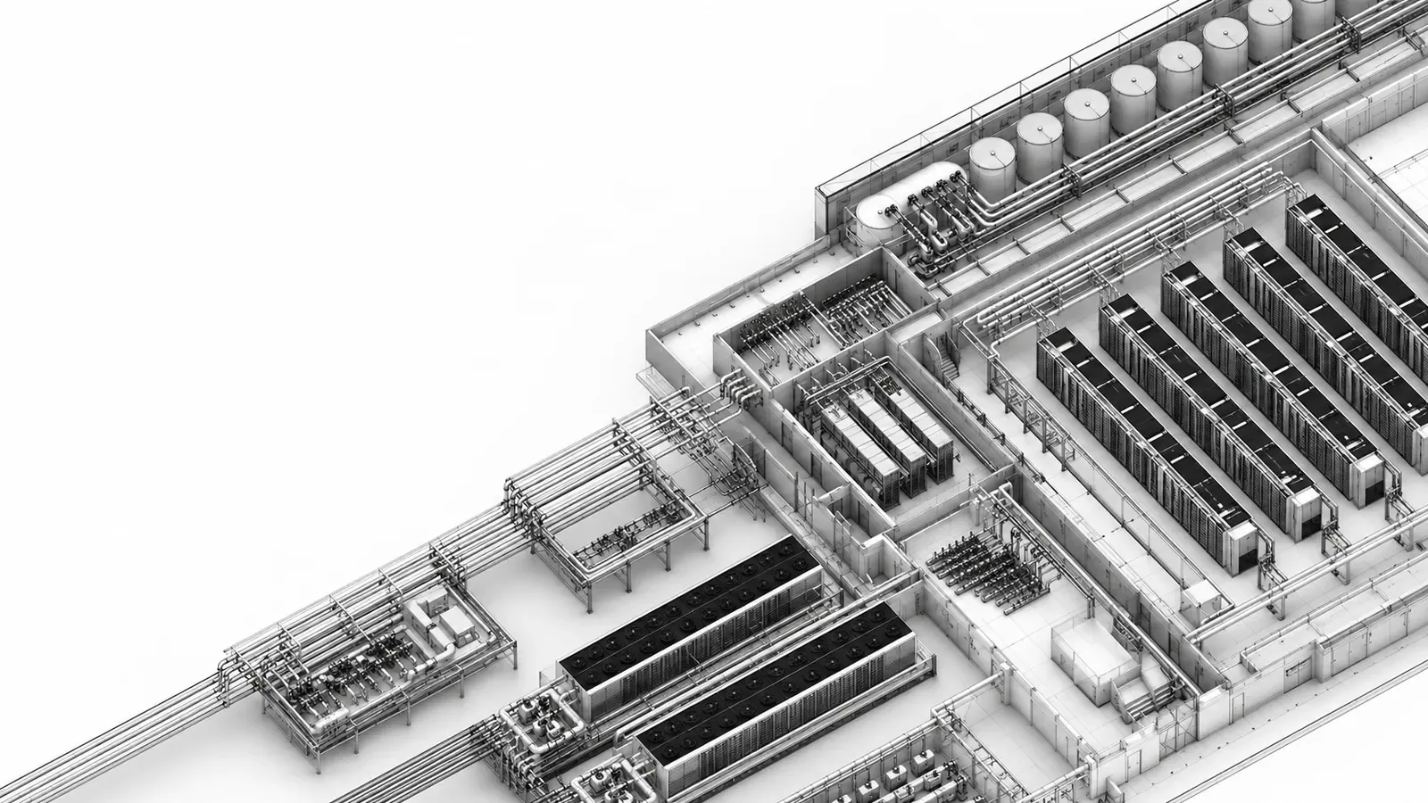
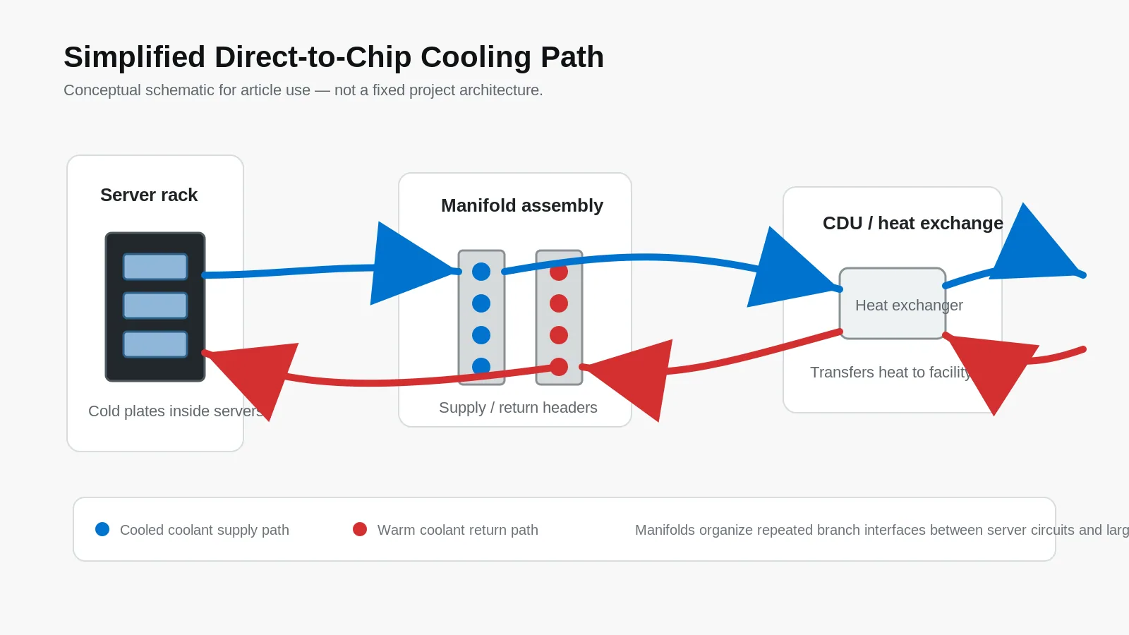
Direct-to-chip cooling moves heat from server components into coolant circuits. Manifolds sit in the repeated interface layer between branch circuits and larger distribution pipework, helping route supply and return paths in a way that can be installed, inspected, and serviced.
The exact loop boundary is project-defined. For quotation and manufacturing review, Chelsey treats the manifold as a hardware package inside the customer-owned system architecture, not as proof that every rack, CDU, facility loop, or cold plate has the same layout.
Paired supply and return headers
Many rack-level or module-level layouts use paired headers: one for the supply side and one for the return side. The paired layout creates a repeatable base for branch positions, isolation valves, test points, mounting brackets, and customer-specified connection interfaces.
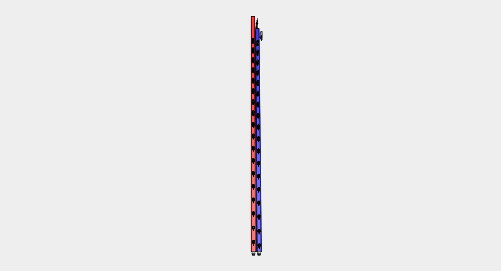
Header spacing, branch pitch, end-connection orientation, and clearance around the manifold all affect downstream assembly. These details should be confirmed in drawings or models rather than adjusted during fabrication.
Branch ports, valves, and connectors
Branch ports connect the manifold to downstream cooling circuits. A branch position may include a welded boss or port, a mini ball valve, and a customer-specified connector, quick disconnect, hose adapter, clamp, flange, or threaded fitting.
Color on valve handles or connector markings is a service aid, not a substitute for a released BOM. Supply and return identification, handle orientation, thread form, connector model, and branch spacing should remain consistent with the drawing package.
- Confirm branch count and branch pitch before fabrication.
- Confirm connector, valve, gasket, and seal material where sourced components are required.
- Confirm whether branch interfaces need caps, labels, flow-direction marks, or service access space.
End connections and service access
Main end connections define how the manifold connects to larger pipework, hose assemblies, CDU-side modules, or rack-side interface hardware. Clamp, flange, threaded, quick-disconnect, and blind-cover choices should be treated as interface decisions, not cosmetic details.
For paired headers, end connections should remain logically matched unless the drawing intentionally specifies different sizes, orientations, or access roles. Random changes to clamp size, tube length, cover position, or connector model can create installation risk.
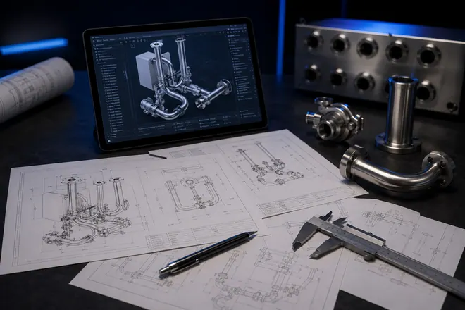
- Use CAD screenshots and drawings as the geometry reference.
- Use product-style renders for communication only.
- Keep customer title blocks and sensitive drawing data out of public article images.
Mounting brackets and clearance
Mounting brackets help fix the manifold to a rack, frame, floor support, skid, or project-specific structure. Bracket spacing and weld location affect access to branch fittings, drains, vents, and end connections.
Clearance should be checked around valve handles, quick connectors, hose bend space, caps, blind covers, and service tools. Chelsey can fabricate the bracketed hardware package, but the installed envelope remains a customer or integrator input.
Fabrication details that affect reliability
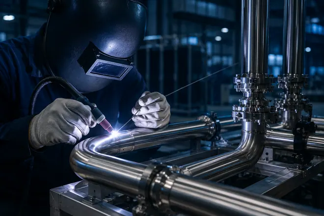
Manifold fabrication is more than placing fittings on a tube. Weld-root condition, stainless contamination control, deburred seal surfaces, thread assembly, bracket welding, cleaning, passivation, and port protection all influence whether the assembly can move smoothly into inspection, packing, and installation.
For stainless liquid cooling hardware, welding, pickling/passivation, cleaning, capping, labeling, and Test support per customer protocol should be treated as part of the fabrication package, not as afterthoughts.
- Confirm material grade and surface finish from the drawing or BOM.
- Confirm whether internal purge, passivation, DI-water rinse, drying, or capped delivery is required.
- Confirm pressure, medium, hold criteria, and documentation under the customer test protocol.
Information to confirm before fabrication
A concise drawing package helps avoid rework. The list below is not a universal design rule; it is a practical input checklist for manufacturing review.
- 2D drawing, 3D model, sample, or interface sketch
- Material grade, surface finish, and wetted-material notes
- Header size, overall length, branch count, and branch pitch
- Valve, quick connector, clamp, flange, thread, or blind-cover requirements
- Mounting bracket position and installed clearance
- Drain, vent, label, cap, and flow-direction requirements
- Pressure, medium, temperature, and Test support per customer protocol
- Cleaning, packing, labeling, quantity, destination, and export protection requirements
Summary
A liquid cooling manifold layout is a physical interface map. Branch pitch, valve orientation, connector choice, end connection, mounting bracket, cleaning requirement, and test protocol all influence how the assembly performs in the next stage of the project.
For drawing-based manifold or pipe module fabrication review, send drawings, models, BOMs, samples, or interface requirements through the RFQ path so the physical build can be checked against the actual project package.