Rubin-Era AI Infrastructure: What 100% Liquid Cooling Means for Manifolds, Pipe Modules, and Facility Loops
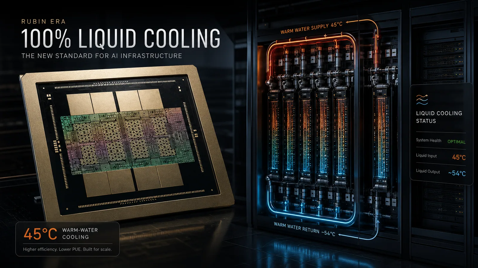
NVIDIA describes Rubin-era AI infrastructure as 100% liquid-cooled. For fabrication teams, the shift puts more attention on manifolds, pipe modules, CDU interfaces, cleanliness, testing, and facility-loop handoff.
Why the Rubin era matters
NVIDIA describes the Rubin generation of AI infrastructure as moving to 100% liquid cooling: chips and networking components cooled by liquid in a closed loop, with no fans anywhere in the system. NVIDIA also says its newest AI servers can run cooling liquid up to 45°C.
For Chelsey, the important point is not a headline about one vendor. It is the manufacturing consequence: when AI infrastructure is designed around liquid paths, the physical interface chain becomes more visible. Manifolds, pipe modules, valve packages, quick disconnects, CDU-side connections, cleanliness, labels, and test documentation all have to be confirmed earlier and more consistently.
From chip heat to the facility loop
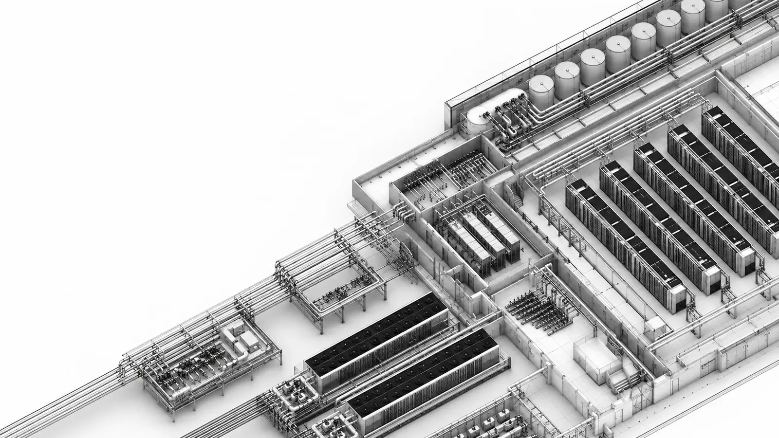
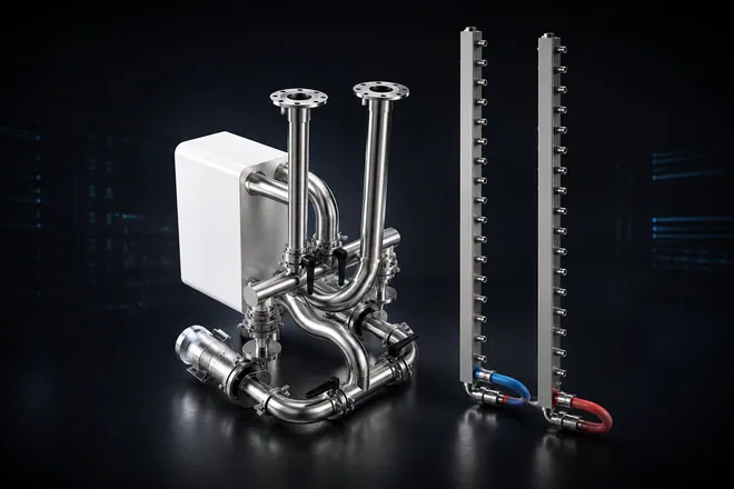
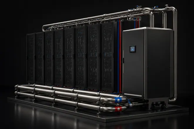
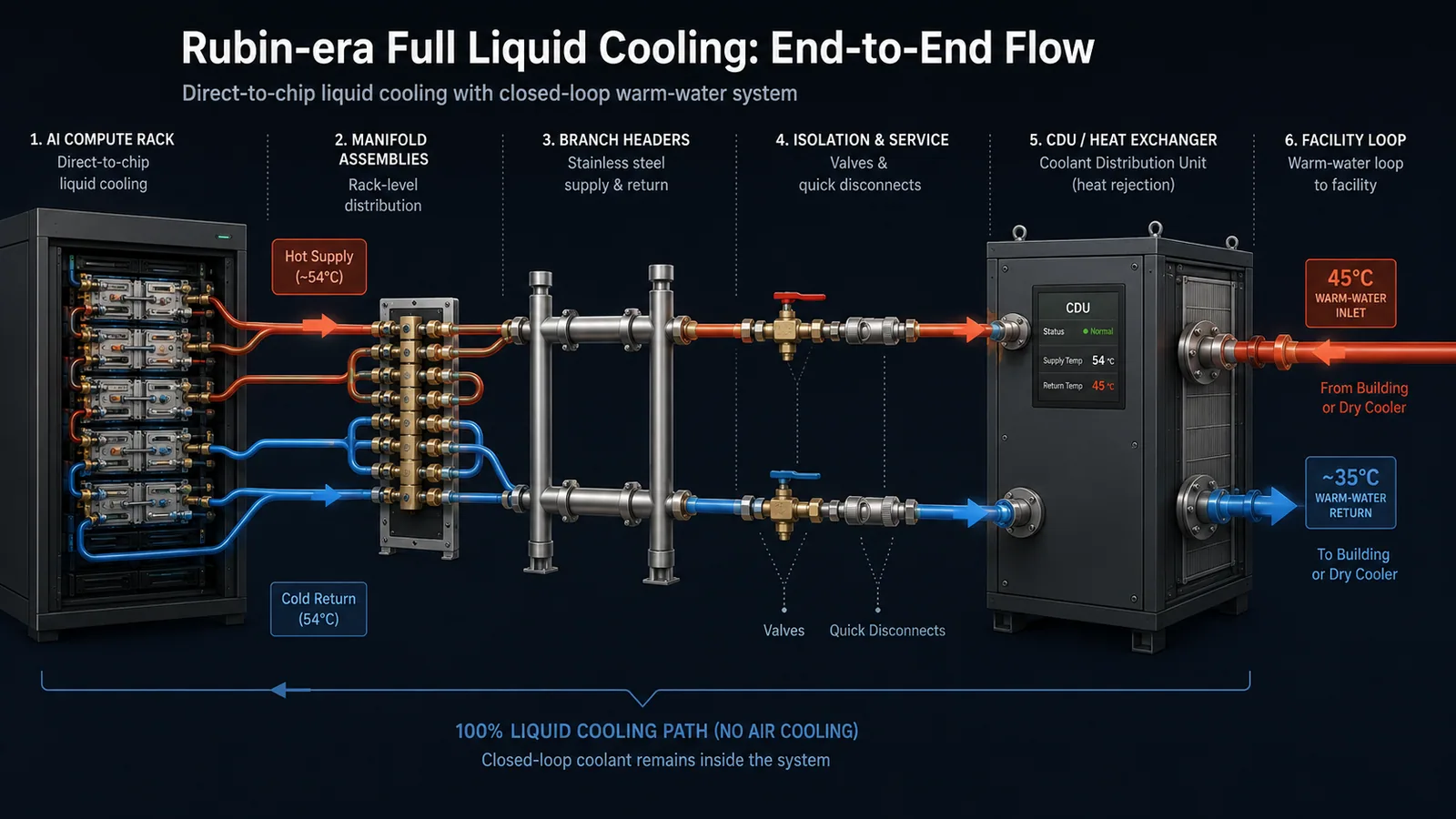
A full liquid-cooling discussion spans more than the cold plate. Heat leaves the processor through liquid-cooled hardware, moves through tray or rack plumbing, reaches manifold and distribution interfaces, passes through service components and CDU-side connections, and is rejected through a facility loop or dry cooler depending on the project design.
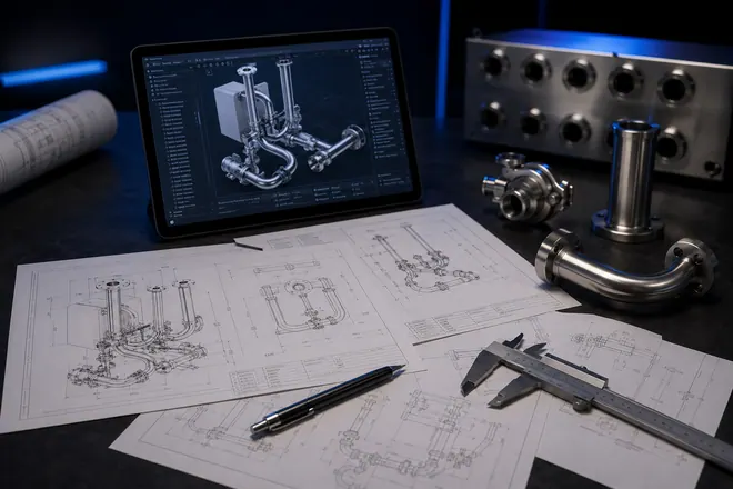
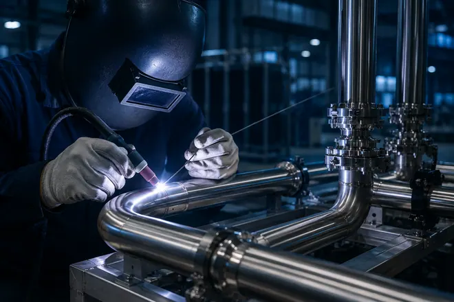
That path crosses ownership boundaries. Platform vendors define server architecture. Operators and system integrators define rack, CDU, controls, facility loop, commissioning, and acceptance. Chelsey stays on the fabrication side: stainless manifolds, prefabricated pipe modules, connection assemblies, component integration, cleaning, Test support per customer protocol, packing, and export-ready delivery from customer drawings or interface requirements.
Why 45°C warm-water operation changes the conversation
Warm-water operation can make cooling infrastructure less dependent on chilled air and mechanical refrigeration in suitable climates. NVIDIA explains that coolant entering a fully liquid-cooled chip at 45°C can leave at roughly 55°C while processors remain within validated operating limits.
For fabrication teams, this does not create one universal temperature or pressure rule. It does make interface discipline more important: material compatibility, gasket selection, seal surfaces, hose or pipe routing, valve orientation, service access, labeling, and test records need to match the actual operating envelope defined by the customer.
What changes for manifolds and pipe modules
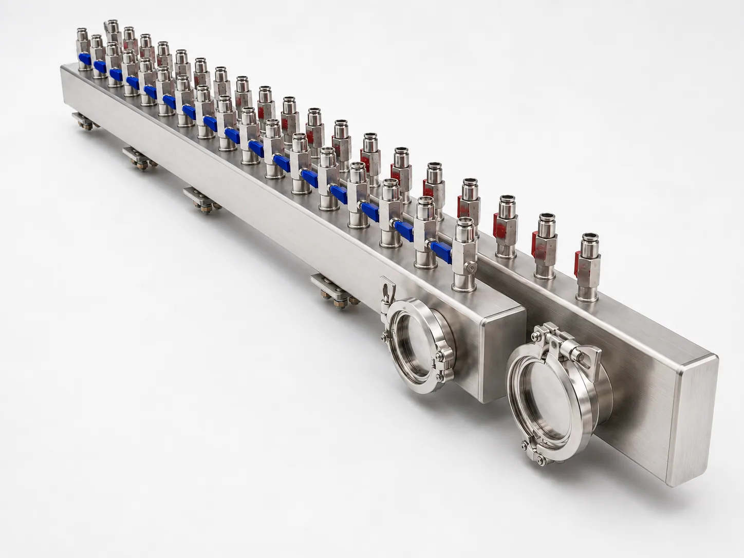
As more rack-scale infrastructure depends on liquid paths, manifolds and pipe modules become repeatable interface hardware rather than secondary accessories. More branch circuits and denser service zones increase the value of a clean, drawing-driven layout.
- More branch circuits require clearer branch numbering, pitch, and supply / return separation.
- Consistent interface positions help installers route hoses, pipe spools, and service tools without improvisation.
- Valve and quick-disconnect discipline matters because serviceable connections multiply across the rack or row.
- Leak-test and pressure-test requirements should be tied to the customer protocol, not guessed from a generic article.
- Internal cleanliness, drying, capping, and protected packing become part of handoff quality.
- Labels, flow-direction marks, and grouped packaging help the next team install the correct hardware in the correct location.
- Drawings, BOMs, and component approvals should be confirmed before fabrication, especially when sourced valves, clamps, QDs, gaskets, or sensors are included.
Manufacturing-side checklist
Before a manifold or pipe module moves into fabrication, the review should focus on what can actually be built, inspected, cleaned, tested, packed, and handed off.
- Released 2D drawing, 3D model, BOM, sample, or interface sketch
- Material grade, wall thickness, wetted-material notes, and surface finish
- Supply / return separation, branch count, branch pitch, and endpoint orientation
- Valve, quick-disconnect, clamp, flange, gasket, thread, drain, vent, and sensor-port requirements
- Mounting bracket position, service access, installed clearance, and hose bend space
- Cleaning, passivation, drying, capping, labels, and protected packing
- Pressure, medium, temperature, hold time, and Test support per customer protocol
Light CTA
If your team already has liquid-cooling drawings, BOMs, samples, or interface requirements, Chelsey can review the manufacturable hardware scope for stainless manifolds, pipe modules, CDU-side connection assemblies, and sourced flow-component integration. The fastest path is to send the drawing package and identify which interfaces, components, testing support, and packing requirements are already defined.
References
NVIDIA Blog, “Hotter Than a Hot Tub: The 45°C Breakthrough to Cool AI’s Biggest Machines,” June 21, 2026. https://blogs.nvidia.com/blog/liquid-cooling-ai-factories/
NVIDIA Technical Blog, “Inside the NVIDIA Vera Rubin Platform: Six New Chips, One AI Supercomputer,” January 2026. https://developer.nvidia.com/blog/inside-the-nvidia-rubin-platform-six-new-chips-one-ai-supercomputer/